


Cost Effective Timber Pile Bridge Repairs

Based on MDOT data
States like Minnesota have hundreds of timber pile bridges. County engineers are responsible to maintain and repair these bridges. Yet, there are few resources that focus on bridge repair. The Minnesota Department of Transportation (MDOT) developed a report that analyzed the number and types of timber pile bridges throughout the state and cost-effective ways to maintain and repair them. This article provides an overview of assessing the condition of pile bridges and maintenance practices and repairs recommended in the MDOT report.
Types of Pile Bridges
Minnesota identified six different types of pile bridges throughout the state. Slab bridges accounted for over two-thirds of the 1,503 pile bridges identified in 2012. There are just under 400 stringer / Multi-Beam or Girder pile bridges. There were less than 30 of the other four types combined. (Girder and Floorbeam System, Truss, Arch, and Culvert.)
Damage Assessment
There are many ways to assess damage to a pile bridge. However, the amount of experience an inspector has greatly impacts the cost and accuracy of the assessment. Multiple types of tests will help pinpoint specific issues and increase the reliability of inspections. It is recommended that a standard set of assessment tools be employed to standardize damage inspections.
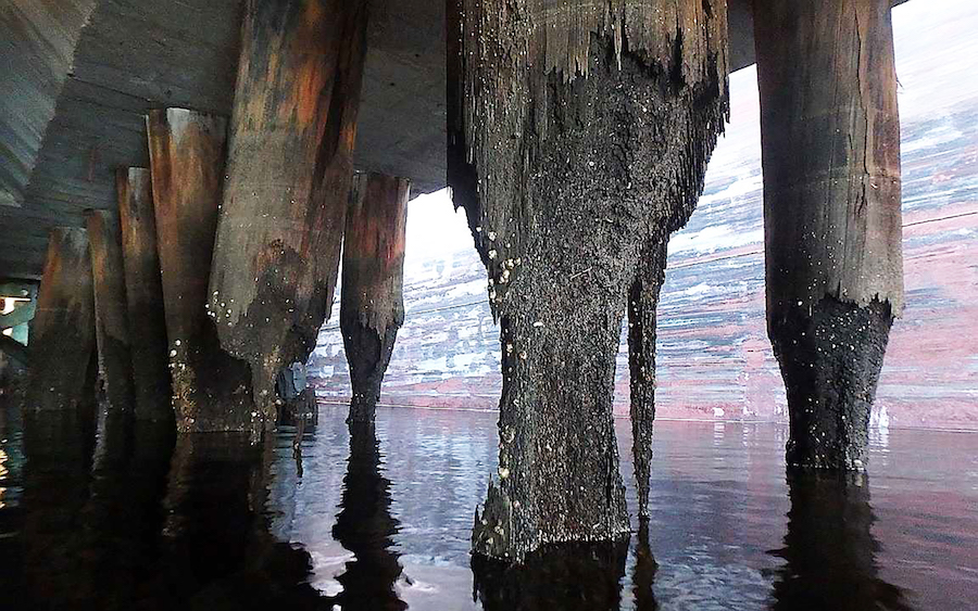
Visual Assessment
An experienced eye can spot many maintenance problems. Color changes in the wood can indicate structural failure. There are several types of corrosion that are visible to the naked eye, such as split, cracked, or crumbling wood. The following visual signs should be noted in the assessment report.
Brown-rot Decay. Wood that is dark brown and crumbly with a cubical appearance. You will see cracks across the grain of the wood.
White-rot Decay. Wood that appears whiter than normal. Unfortunately, white-rot can be deceiving as it retains its shape and size until it is severely degraded.
Soft rot decay. You will typically see this type of decay at the water line. It is a shallow zone of decay on the wood surface that feels soft in the area that is wet. However, it is firm immediately below the surface.
Staining. Wood staining is usually seen on areas that have been wet or where water is trapped. The staining is caused by mold or stain fungi, watermarks, or rust stains from metal fasteners.
Salt abrasion. The wood will have a fuzzy appearance. This can degrade the preservative’s protective barrier.
Identifying Defects
Following are physical properties and defects that can may indicate areas of concern and should be noted and scheduled for future maintenance inspections.
Checks: Separations in the wood that run parallel to the growth rings at the end grain of a bridge member.
Decay at Fasteners: Deterioration found at the holes and cuts used to connect the wood bridge members.
End Grain Decay: Deterioration at the ends of the timber members that extend into the member that is parallel to the wood grain.
Splitting: Damage that extends perpendicular through the board to an adjacent face.
Surface Decay: The exterior of a timber member can deteriorate from various sources including insects, mold, sapwood stains, and microorganisms that feed on wood.
Ultraviolet Degradation: The surface of the wood turns gray from weathering.Testing
There are various methods available to test the wood to identify the specific type of deterioration, if any. Some of these tests are subjective. Other tests use tools that specifically measure the potential source of the deterioration, such as an electronic moisture meter.
Probing and Pick Tests
Probing
Use an inspection probe to find pockets of decay near the wood’s surface. You can also test for splinter patterns. You will not be able to easily probe wood that is not decayed. Probing may break the wood. Fibrous breaks are long and they separate from the wood’s surface at a distance from the probing tool. Splintering breaks result in splinters that fall right on top of the tool.
Pick
A pick test is a subjective test that requires the inspector to make a judgement on the presence and type of deterioration based on sound. If picking at the wood with a sharp tool (such as flathead screwdriver or pocketknife) results in few (or no) splinters, the sound will be subdued.
Moisture Measurement
Use an electronic hand-held moisture meter to determine the moisture content of a wood member. Two metal pins are driven into the wood. The meter measures the electrical resistance between the pins. The result is displayed on the meter’s screen. Moisture content above 20% provides an environment where decay will begin. You can use this method to determine where moisture is trapped. High moisture content indicates that additional assessment is needed.
Sounding
Sounding requires that you strike the surface of the wood with a hammer. If you hear a hollow sound, this indicates a pocket of decay. Solid wood will not sound hollow. Experienced inspectors learn to hear the difference. It is recommended that sounding be used with other tests.
Stress Wave Devices
A stress wave device measures how long it takes for stress waves to travel through a wood member. This test identifies voids in the wood caused by decay. Stress waves going through deteriorated areas move very slowly. The wave signals cannot determine whether the cause is due to active decay, ring shakes, or other problems. Also, a single wave measurement will not detect internal decay 20% or below the total cross-section of a timber pile. So, it should be used along with other tests. You must be able to access the complete circumference of the pile in order to perform this test.
Drill Resistance Devices
In this test, you document the resistance needed to drill through a wood member. Less resistance indicates lower density and likely deterioration. This method is less invasive since the drill bits are small. As well, the cross-section of the drilling location can be accurately defined. It, too, should be used with other testing methods.
Core Boring
Incremental samples are taken perpendicular from the face of the wood member. Immediately insert a wood plug into test holes. The plug should be treated with a preservative that works as well as the preservative that was originally applied to the sample. Visually inspect the cores for deterioration. They can be sent to a lab for biological and chemical analysis.
This method is not often used since drill resistance devices give reliable information with far less damage to the wood.
General Timber Maintenance
Routine and periodic maintenance goes a long way in reducing the need for bridge repair.
Moisture Control
The single most effective way to keep timber healthy is through moisture control. It is best that the timber abutment be placed far from stream banks, where possible. Existing piles that are regularly going through wet and dry cycles should be inspected more often.
End Grain Treatment
Protect the cut ends of timber members by brushing on a timber treatment or capping with tin or aluminum flashing. This reduces water exposure.
In-Place Treatments
There are several types of in-place treatments to prevent deterioration. A few examples include paste, surface treatments, and fumigants. Pile tops cut to length, end-grain joints, and the area around fasteners should be retreated with a preservative right after installation.
Fastener Maintenance
Ensure structural fasteners are tight and test them for corrosion. Retighten fasteners as needed. Replace highly corroded fasteners.
Maintaining Superstructure Elements
Outside Timber Stringers
A timber bridge’s outside stringer is more likely to deteriorate as it is highly exposed to rain, sun, and debris flow. In addition to removing dirt and loose decayed material, it is recommended that flashing be installed along the timber stringer. This will reduce the amount of moisture intake.
Maintain Deck Drainage
Road debris, gravel, and sand can block the bridges’ drainage system. Keep the bridge and, where installed, scuppers clear of debris. This allows the water to flow freely off the bridge.
Removal of Deck Vegetation
Another consequence of not keeping the bridge clear of debris is that it provides the dirt and water vegetation needs to grow between gaps in the deck boards. This vegetation should be removed along with the debris.
Substructure Elements
Removal of Debris from Pile Caps
Gaps between the deck boards will allow some debris to fall on top of pile caps. This can trap water against the pile cap and cause it to deteriorate faster. If the debris is not regularly removed, the pile cap can deteriorate enough to compromise the support of the superstructure. Regular maintenance can avoid (or delay) the need to install a new pile cap.
Repair Small to Medium Cracks
Decay fungi can enter untreated cracks and splits in the wood at the timber pile’s core. These cracks and splits should be filled with epoxy grout. This will seal the area and keep out water and debris. It can be used to bond sections that have separated, increase shear capacity, and reduce future splitting. Inject low viscosity epoxy into the void and seal it with a sealing epoxy.
Strengthening Bridge Superstructure Elements
The following are general concepts. The county engineer will determine the final design, material specifications, and products to be used for a specific pile bridge. The repairs covered are not an exhaustive list, but those identified by a Minnesota county engineer survey as seen most often in their state. It is assumed that these types of repairs are likely common in timber pile bridges in other states.
There are two main types of superstructures that will be discussed: Dowel-laminated decks (a.k.a. Wheeler decks) and timber stringers. Deterioration to either may compromise a pile bridge’s strength.
Repair of Laminated Bridge Decks
To reduce weakening of the deck, the repair patch to the transverse members should be a maximum of five feet long and three feet wide. Replace the deteriorated material with sound wood and reinforce with a concrete patch or epoxy polymer.
For small partial-depth repairs, install galvanized lag bolts into pre-drilled holes. Add a wire-tied, welded wire reinforcement mat to the lag bolts. For full-depth repairs, use an approved construction adhesive to add reinforced steel attached to both ends of the remaining sound material.
Strengthening of Individual Timber Stringers
For minor to moderate deterioration that has weakened the strength of members at the ends along the span, attach steel members to the timber stringer or girder. To simplify construction, use bolts or lag bolts rather than through rods.
Increase shear capacity at the end of the beam by adding fish plates, steel plates, or channels to each side of the stringer. For additional tensile strength, use timber fish plates, steel plates, or angles. Any added elements should extend out at least two feet from either side of the deteriorated area. Add holes for drainage for members attached to the bottom to reduce future deterioration to the repair.
Strengthening and Rehabilitation of Bridge Substructure Elements
There are several repair methods to strengthen substructure elements.
Add Steel Channels to Piles
This method is appropriate for damage up to 18 inches. Attach steel channels to timber pile with bolts or lag bolts.
Add Steel sisters for pile reinforcement
Determine the required capacity to bring the pile up to code. Size steel channels to place on each side of the pile. The channel should extend two feet beyond the deteriorated section on each side. Attach the channel with enough bolts of the proper size to the pile. Weld 1x1x1/8-inch angles to the web of the channel equally spaced between the rows of bolts. Notch the pile to accept the angle. Be sure to apply a preservative treatment at trimmed and notched areas.
Add Reinforced Concrete Jackets to Piles
Partially encase the timber piles with a concrete-filled steel shell. Minimally, a six-inch thickness of encasing concrete is recommended. For example, a 24-inch corrugated metal pipe (CMP) for a 12-inch diameter pile. Install L-shaped bolts into the pile radially at quarter points with an epoxy resin. Attach a longitudinal reinforcement bar to the bolts with wire ties. Spirally wrap the steel cable around the reinforcement. Use a slope-top edge so water will shed away from the pile. Split the CMP into two halves and place it around the pile. You can use steel banding, double angles, and bolts to attach them together.
Encapsulation of Pile Groups
With this method, multiple damaged piles are encapsulated in a reinforced concrete-grade beam. This strengthens the overall pile group. At least 12-inches below the damaged area should be removed. (Below the ground surface or below the pile group — whichever is lower.) A cofferdam may be used for piles that are submerged. The area will need to be dewatered. Thread horizontal reinforcing bars through drilled holes in the piles. Place a second set of reinforcing bars beyond the face of the pile with lag bolts. These should be attached to the pile face as standoffs. Place concrete around the piles and slope away the tops from the piles to achieve proper drainage.
Conclusion
Regular inspection of pile bridges is key in reducing the overall cost of maintenance and repair. As well, proper and careful repairs will ensure that pile bridges remain safe throughout your state.
How can visual assessment help in identifying potential issues in timber pile bridges, and what are the visible signs of decay inspectors should look for?
Visual assessment aids in spotting maintenance problems such as color changes, cracks, and corrosion, with visible signs including brown-rot decay, white-rot decay, soft rot decay, staining, and salt abrasion.
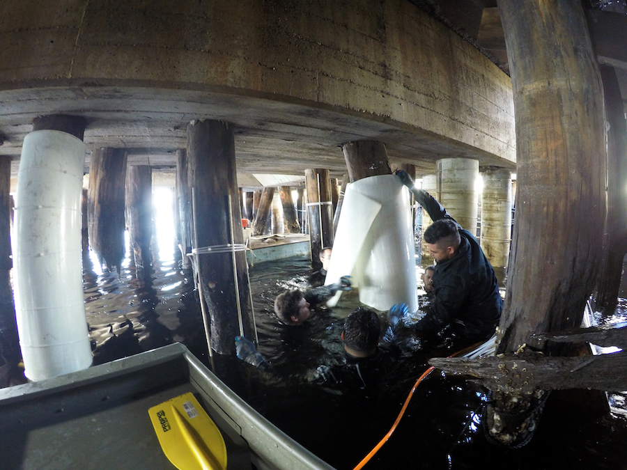
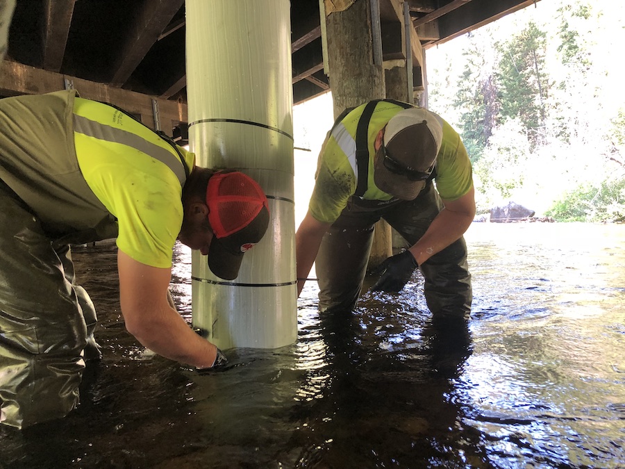
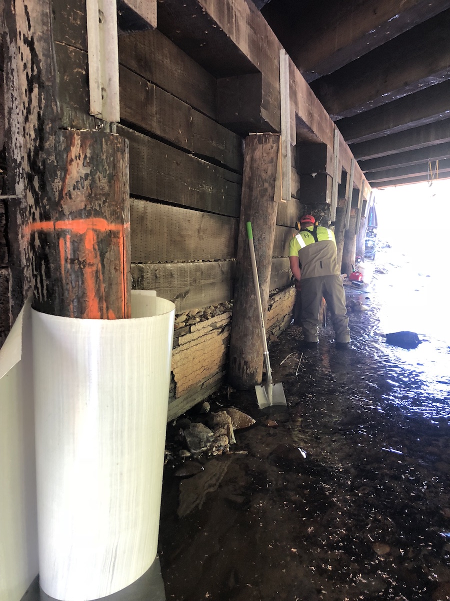
What are the recommended methods and tools for testing timber piles to identify deterioration, and how can the PileMedic® system assist in efficiently repairing timber marine piles?
Recommended testing methods include probing, pick tests, moisture measurement, sounding, stress wave devices, drill resistance devices, and core boring; the PileMedic® system from QuakeWrap offers a patented solution for quick adaptation to field conditions when repairing timber marine piles with laminates for enhanced strength.