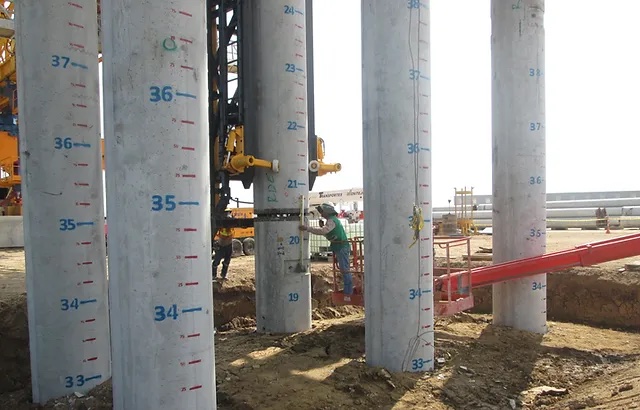
Pile Driving Part VII: Pile Driveability
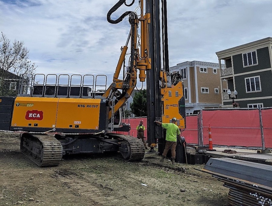
View the complete article here.
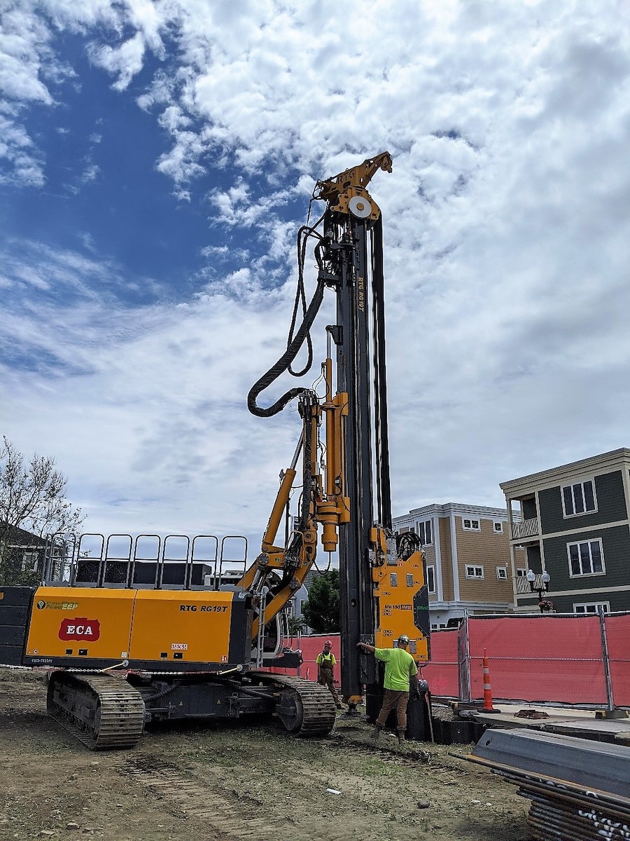
Dynamic Analysis
Piles penetrate the ground by dynamic means such as impact or vibration. Obtaining a successful pile foundation, which meets the design objectives, depends largely on relating the static analysis results presented on the plans to the dynamic methods of field installation. Dynamic analysis can provide answers to the following site-specific questions:
- Can a given pile be driven to the estimated depth and capacity with a specific hammer?
- If so, what will be the set (deflection) in the final blows and what will be the maximum stress experienced by the pile?
If driving cannot be accomplished as specified in (1), what hammer characteristics are needed to successfully complete the project with the pre-selected pile? Alternatively, what other pile of the same length can, perhaps, be driven with the hammer first considered?
To answer these and other questions that may appear in connection with a particular piling project, rational analysis based on the hammer-cushion-pile- soil system (dynamic analysis) is useful. Dynamic analysis should be performed during both the design and construction stages of a project.
Pile Driveability
The limiting pile drivability for a specific pile-soil situation is the maximum soil resistance to which a pile can be driven without damage. The soil resistance developed is a function of the pile dimensions and the subsurface profile. An exception to this maximum is a pile penetrating very soft soil to bear evenly on sound un-weathered rock with no transition zone of weathered rock. In this special case, the full structural strength of a pile can be developed without significant driving effort.
Factors Affecting Driveability
To perform successfully, a pile must satisfy two aspects of drivability: (1) the pile must have sufficient stiffness to transmit driving forces large enough to overcome soil resistance, and (2) the pile must have sufficient strength to withstand the driving forces without damage. For a given soil condition and pile length, the strength and stiffness of a pile determine its drivability.
It is important to recognize that even if the static structural and static soil capacities allow an increase in pile stresses, it may not be possible to develop the increased pile loads because the resulting driving stresses would exceed allowable pile driving stress limits.
The limitations on maximum allowable static design stresses in pile materials by various codes generally represent the static stress levels (static load capacity), which can be consistently developed with common driving equipment and methods.
Methods for Determining Driveability
There are three available methods for evaluating drivability:
Static Load Tests
Static Load tests are useful for checking drivability prior to production pile driving. Test piles are normally driven to pre-determined lengths and load tested. Load tests can be performed during design and/or construction stages.
Wave Equation Analysis
This method accounts for pile stiffness and predicts driving stresses as well as the relationship of hammer blow count versus ultimate pile capacity. It can be used to check drivability in advance of driving, to design the most economical pile wall thickness or pile section, and to select driving equipment.
Dynamic Measurements
These measurements and their analysis can be used to measure the driving stresses and static bearing capacity of piles during driving. It can also provide static soil resistance distribution and damping parameters for a wave equation analysis. Hammer and driving systems performance can also be evaluated from the measurements.
Driveability and Pile Type
Drivability should be a consideration in the design of all driven piles. It is particularly critical in the case of cast-in-place concrete filled pipe piles, wherein only the stiffness of the steel casing is available at the time of driving.
Single-material solid-section piles such as steel H, precast concrete, and timber are subject to drivability limitations, particularly as allowable design stresses increase. In the case of long prestressed concrete piles, drivability is normally limited by the pile’s compressive strength, but tensile strength will be critical in the early driving condition where large hammer energies may be imbalanced to the small soil resistance.
Mechanical Efficiency
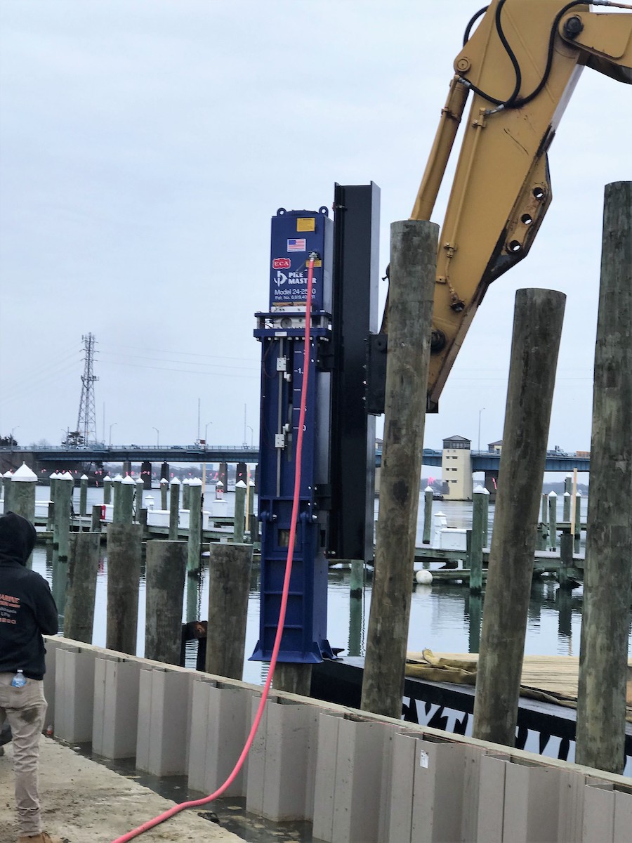
Mechanical losses are inevitable in any type of machinery. In pile driving equipment, they can be due to frictional losses between the moving (ram) and stationary (frame) parts, losses due to back-pressure in the valving of air/steam and hydraulic hammers or the exhaust ports of diesel hammers, and other sources. These are a function of both the design of the equipment and the way in which it is maintained.
Net Striking Energies
A recommended way to evaluate hammers based on their impact energies is to compare their net striking energies rather than their efficiency. Of course there are other factors to consider, such as the relationship of the (effective) stroke to the ram weight, type and size of cushion material and the effects of the necessary compression in diesel hammers. Wave equation analyses are usually based on rated striking energy times an efficiency, which yields a net striking energy.
Batter Piles
Another factor in the reduction of output energy occurs when driving batter piles. This is generally considered an “efficiency” factor but strictly speaking is not. It comes from the geometry of the hammer relative to the gravity field and is most pronounced with single-acting hammers.
Hammer Size Selection
It is important that the contractor and the engineer choose the proper hammer for efficient use on a given project. A hammer that is too small may not be able to drive the pile to the required capacity or may require an excessive number of blows. On the other hand, a hammer that is too large may damage the pile. A wave equation analysis, which considers the hammer cushion-pile-soil system, is the recommended method to determine the optimum hammer size.
Dynamic Analysis by the Wave Equation
The wave equation analysis is now the standard method of predicting drivability in anticipation of pile driving. It is used to obtain the following information for a single blow of the hammer:
- To predict the driving stresses induced in the pile.
- To determine the resulting motion of the pile during the impact.
- To determine the resistance to penetration afforded by the soil at the time of driving.
- To estimate the transferred energy delivered to the pile top.
This information then enables the engineer to answer such questions as:
- Can a given hammer drive the pile to the required depth?
- What rate of penetration will the hammer provide, i.e., how long will it take to install the pile?
- To what maximum penetration can the pile be driven?
- What is the maximum soil resistance to penetration that the hammer can overcome?
- Will excessive stresses be generated in the pile or hammer during driving?
Wave Equation and Design
The wave equation is also often used as an aid in design. For example, it is commonly used:
- To indicate the blow count required for penetration of the pile afforded by an estimated soil resistance at the time of driving.
- To optimize the cushion, i.e., to determine which cushion will effectively limit the driving stresses induced in the hammer and pile, and yet will still produce the maximum possible permanent pile set per blow of the hammer.
- To determine the correct size of the driving hammer. This reduces the chance of selecting a very large and expensive hammer whose capacity is not needed and whose use would cause pile damage. The more unfortunate situation is selecting a small hammer whose driving capacity is found to be inadequate to drive the pile to the required resistance or depth.
- To determine the influence of the driving accessories. It has been shown that in many cases the driving accessories absorb a major portion of the total energy output of the hammer. In some cases, these accessories account for a 50% reduction in the energy output of the hammer. The use of the wave equation enables the selection of optimum driving accessories required to minimize these losses.
The wave equation is also a powerful engineering aid for the foundation designer since numerous alternative designs can be quickly studied at very little expense. Such a study greatly increases the probability that the final design will be economical and that installation problems will be minimized.
Hammer Selection: Vibratory hammers
High installation rates can be achieved with vibratory hammers under certain conditions. This makes them attractive for installing piles. Toe resistance of the pile is a major consideration in the selection of the vibratory hammer. Using a vibratory hammer is particularly successful with piles that have small toe areas, such as sheet and H-piles. However, soil type should also be a key consideration, as follows:
- Loose, wet, granular soils (including gravels): Vibratory hammers are extremely effective in this type of soil.
- Soft and low plasticity clays: Vibratory hammers generally work well.
- High plasticity clays, hardpan, and decomposed rock: Vibratory hammers perform poorly in these types of soil because of their limited “chopping” effect (as compared to an impact hammer). If use of a vibratory hammer is desired in such soils, a heavier model with a large amplitude of oscillation should be specified.
Vibratory Hammer Size
Soil conditions have a greater effect on the size requirement for the vibratory hammer than pile length. Examine the boring logs – if the material is loose or medium coarse sand with some moisture, driving should be easy, and a smaller vibratory hammer is required. On the other hand, if the material is very stiff or hard clay, driving will usually be difficult. Clay doesn’t necessarily mean that a vibratory hammer will be effective. Where there is sufficient moisture content, plasticity is low, and the vibratory hammer is large enough. Here amplitude is important; a very satisfactory result can be achieved with a vibratory driver.
Conclusion
Many successful pile contractors use the wave equation analysis to check and improve upon an engineer’s pile design, for preparing bids, to avoid construction problems and to select the most appropriate pile hammer for the given project conditions. To achieve economical pile design, the engineer must match soil resistance, pile stiffness, pile strength and driving equipment. Failure to correctly understand the important physical concepts often results in project delays, claims, and additional costs.
View the complete article here.
When should dynamic analysis be performed?
Dynamic analysis should be performed during both the design and construction stages of a project.
How many methods are there for evaluating pile drivability?
There are 3. Static Load Tests, Wave Equation Analysis, and Dynamic Measurements.

